
*This information is as of September, 2025. All specification and contents are subject to change without prior notice.
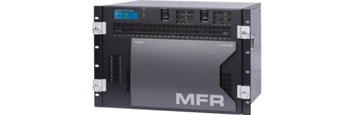
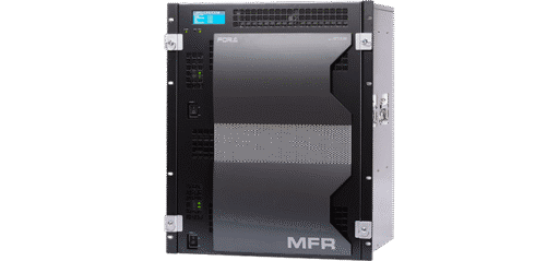
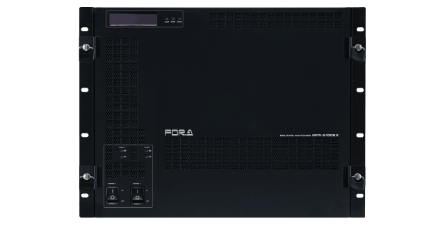
MFR-5100EX is a multi-format routing switcher supporting 3G-SDI, HD-SDI, SD-SDI, ASI, MADI, and AES. Inside the 8RU case a matrix of up to 128 inputs/128 outputs can be configured. Furthermore, multiple units can be linked to expand the matrix and provide redundancy, making it a flexible core product for system integration.
Multi-Format Support
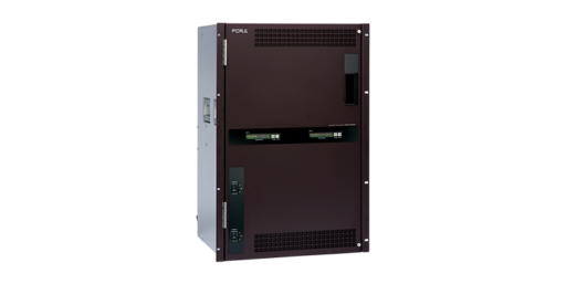
Expandable up to 16 systems per card. Up to 8 input cards and up to 8 output cards can be installed. It allows for a maximum 128×128 matrix configuration. By using an audio-supported card, video and audio routing can be handled within a single chassis, making it easy to perform linked switching of video and audio.
Video input/output card
Support for 3G-SDI(Level-A/B), HD-SDI, SD-SDI, ASI input and output. With auto signal detection, there’ s no need to worry about signal formats.
- MFR-16SDIB: 16-input card enables support for 3G/HD/SD-SDI and ASI
- MFR-16SDOA: 16-output card enables support for 3G/HD/SD-SDI and ASI
Audio input/output card
Ready for audio input/output cards that support MADI, AES/EBU, and analog audio. This allows for A/D and D/A conversion, MUX/DEMUX plus embedding, de-embedding.
- MFR-16AAIEX: Input card for 16 analog audio embed to SDI signal
- MFR-16AESI: Input card for 16 AES/EBU stereo pairs (32 channels)
- MFR-16SDIB: Input card for 16 MADI (64 channels)
- MFR-16AAOEX: Output card for 16 AES/EBU stereo pairs convert into analog audio
- MFR-16AESO: Output card for 16 AES/EBU stereo pairs (32 channels)
- MFR-16AESPO: Output card for 16 AES stereo pairs (32 channels) with audio mapping function
- MFR-16MADIPO: Output card for 16 MADI with audio mapping function
Configuring Matrix
(up to 128 Input/128 Output)
The input/output board has 16 channels and up to 8 boards can be installed together. As a result, matrix of up to 128 input/128 output can be configured.
Multi Viewer function
An optional built-in multi viewer is available. It can output up to 4 video systems without using any destination ports.
Outstanding Redundancy
Since routing switchers are the core of large video systems, we have engineered a variety of features to ensure full redundancy.
Redundancy Features
- CPU board redundancy (optional): a secondary CPU board constantly monitors the operation of the primary board. If the secondary CPU board detects any faults, operation is immediately switched to the secondary CPU to allow for continuous operation without down time.
- Redundant power supply (optional): in the rare event of a power supply problem, the second supply takes over to avoid any interruption of router function.
- Network redundancy (optional): a secondary Ethernet connection provides back-up for system control. With CPU redundancy, each interface can also have a backup (for details see below).
- Linking multiple units allows for matrix expansion and redundancy.
Interface details
| Connector | Standard configuration | With redundant CPU installed | |
|---|---|---|---|
| Ethernet | RJ-45 | 2 | 4 |
| Serial | 9 pin D-sub (male) | 1 | 1 |
| Alarm output | 9 pin D-sub (female) | 1 | 1 |
High maintainability
All boards and power units can be changed from front side without disconnection of rear cables. This simplifies any maintenance required.
Various Crosspoint Control
A variety crosspoint control features are possible in addition to normal crosspoint switching.
- Salvo function:
(1) Button-assigned Salvo: multiple crosspoints can be assigned to any button. Separate settings can be made for each remote unit.
(2) Main unit storage Salvo: multiple crosspoints can be stored on the main unit side and shared by all remote units. - Take operation: after presetting crosspoints, press the Take button to change the set crosspoints.
(1) Mode-switching Take button: switches between take operation and usual operation (instant execution).
(2) Always Take button: always performs take. - Link function: this can group and link multiple crosspoints.
- Level operation: level switching allows separate control over different subject types.
- Chop function: allows user to switch between two sources for a destination.
- Monitor out: enables output of any destination source to a dedicated monitoring channel.
- Prevention of incorrect operation:
– Inhibit: Crosspoint, Source, Destination
– Lock: Lock Other / Lock All / Lock Local
Matrix Partition Function
One routing switcher can be virtually partitioned to build any theoretical hierarchy, creating possibilities for use in various operations.
Examples:
- 4K/8K-supported routing switcher: supports 4K and 8K signal switching with simultaneous control of multiple cross points.
- Fully independent switching: a single unit can be used as multiple routing switchers by making multiple matrix partitions. This is effective when you wish to do multiple operations while avoiding source sharing.
- V/Key linking switcher: allows two inputs to be linked for routing of video and key signals together.
- 3D switcher: partition the matrix in two and control the left and right channels from a 3D source simultaneously.
- HD/SD simul-switcher: provides simultaneous control of HD and SD sources. Perfect feature for HD/SD master control switching.
SNMP Support
Remote monitoring by SNMP is supported and the router can easily be integrated into an SNMP monitoring system. In this way you can monitor the status of various items including: power source, fan, CPU, presence/absence of signals, crosspoint errors and more.
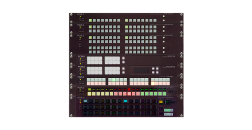
Remote Control Units
We offer several types or remote control unit to suit your application. The number of units that can be connected is a maximum of 128, including the main unit. This lets you build a flexible control environment by the way you partition the matrix and make operation level settings. Please refer to MFR-RU series page for the lineup and details.
Interface Expansion Unit
The interface expansion unit lineup includes 3 types to suit your specific application. The number of units that can be connected is a maximum of 128, including the remote control units.
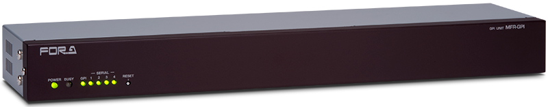
MFR-GPI: GPI Unit
Provides an interface for GPI control. This 1 RU sized unit is equipped with user-assignable GPI/O (128 channels) and 4 serial ports (9-pin D-sub male). It can be used for setting Input/Output and supports system configuration.
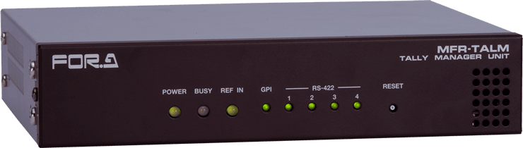
MFR-TALM: Tally Manager
MFR-TALM is a device for performing central management of tally and material names of the MFR main unit and peripheral devices (such as video switchers and multi viewers). MFR-TALM performs the tally calculation, which were originally performed by the MFR main unit, so that the tally linking can be speeded up.
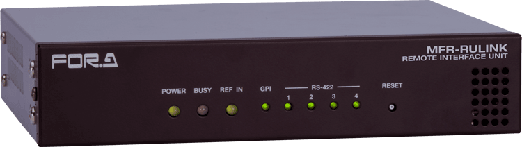
MFR-RULINK: MFR Remote Relay Unit
The MFR-RULINK connects MFR main units to MFR remote control units that are located in distant locations. Operations such as Cross point switching or Lock can be performed with MFR-RULINK using MFR remote control units from a distant location. (MFR-3100EX/5100EX/5000/8000 supported)
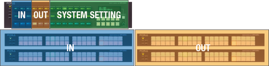
Supports Combinations of Multiple Remote control units
Multiple remote control units can be combined to make them function as a large scale control panel.
Combination example:
For 128 x 128 full control + system settings:
MFR-40RU x 4 + MFR-39RUA x 1
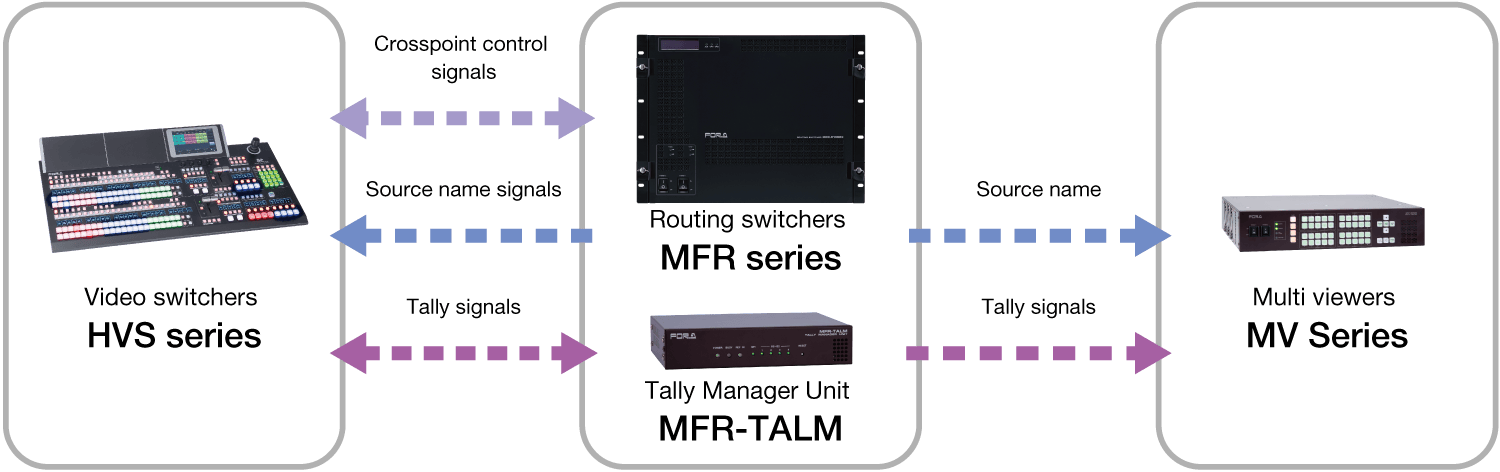
System linkage with other products
for flexible system operation
MFR series can be linked with other products including FOR-A video switcher HVS series or multi viewer MV series via LAN or serial port.
- MFR routing switcher crosspoints can be controlled from HVS video switchers.
- Integrated management of source names by MFR, which automatically send source names to HVS and MV multi viewers.
- HVS and MFR exchange tally information with each other.
- Source names and tally linkage between MFR and MV are controlled by TSL protocol.
Support varies by model and function. For details, contact your FOR-A dealer.